News, 22 January 2022
News, 22 January 2022
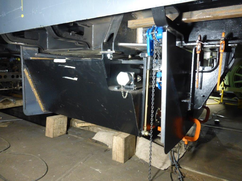
More tank news this week; the Cl. 158 tank we're using (at a significant saving over the manufacture of a bespoke tank) is now fully mounted for the first time. Here is it seen supported at the far end of the photo by a bracket which exactly replicates the original Baby Deltic type and at the near end by new hangers to pick up the original mountings for the 158 tank. The far end bracket is attached to a replica Baby Deltic bracket as it would have been on the original locos. The near end hangers are laser cut then welded together to form the assembly seen below. The shiny bolt goes through the final part of the hanger (the bolting plate) which is fully welded to the two cheek plates above it.
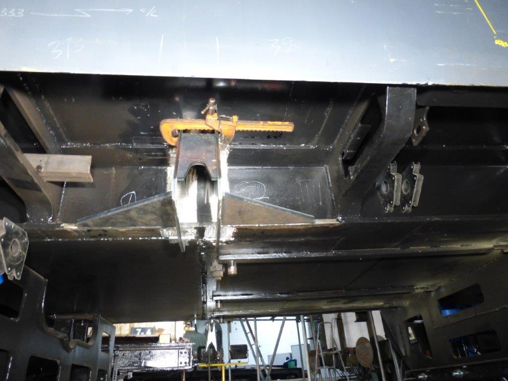
The chain hoist is holding the dummy tank end in position to allow the accurate location of the (not visible in this photo) bracket which will sit on the original Cl. 37 (identical to a Baby Deltic) underframe bracket, itself seen here held in position temporarily by Carver clamps.
Once all the correct positions of the dummy tank ends, brackets and underframe brackets is confirmed they will be welded onto the tank and drilled / bolted to the underframe respectively.
This (below) is the second 'cheek plate' for the tank hanger tacked into place. The one to its right was done first and a spacer used between the pair to set the correct separation. It should be noted that the tack at the very top in this photo is on a plate joint above it. This weld, and the seam which was added later, does almost nothing for the strength of the mounting, being attached only to the engine room floor above it. The strength of the completed assembly is almost all in shear along the web of the I beam which forms the loco longitudinals.
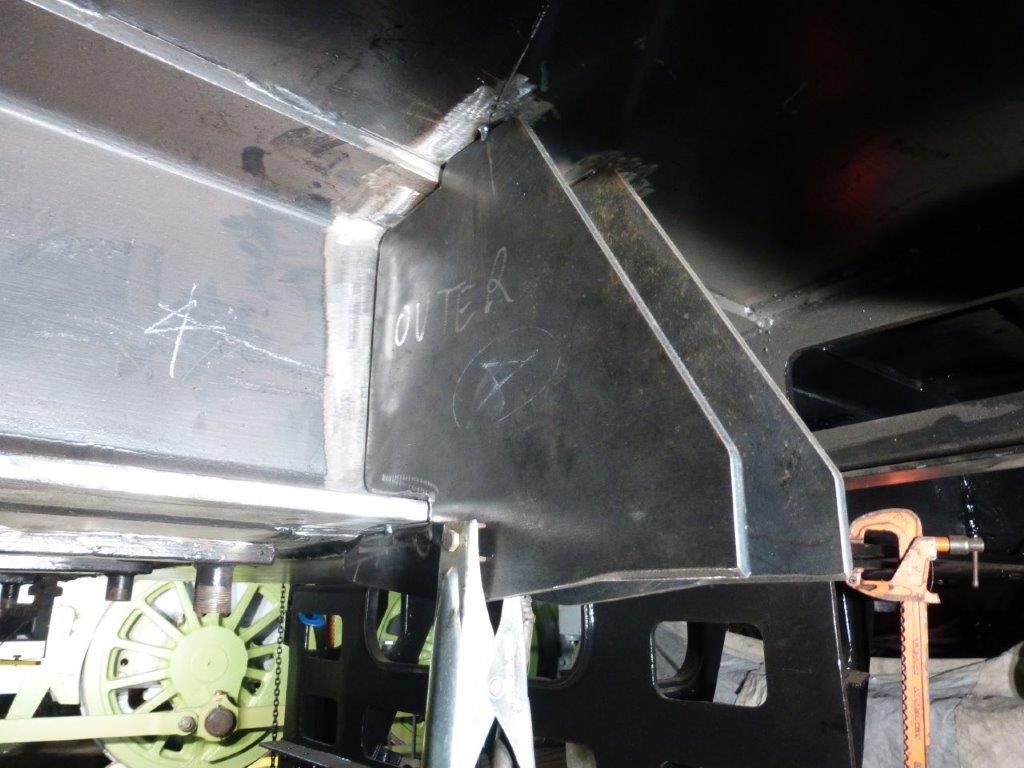
Added to the assembly are two (one either side of each hanger) shear plates whose only job is to prevent longitudinal distortion in the event of an incident resulting in serious deceleration - i.e. a collision / derailment. The total gross weight of the tank and all the dummy cladding assemblies is less than 3000kg, the shear plates are 15mm thick, there are four of them and they are fully welded to the longitudinals, the bolts (M18 x 12.9 grade) will shear off before the mountings do.
The bolts shown in the first photo of are 8.8 grade and are temporary for use during the build stage.
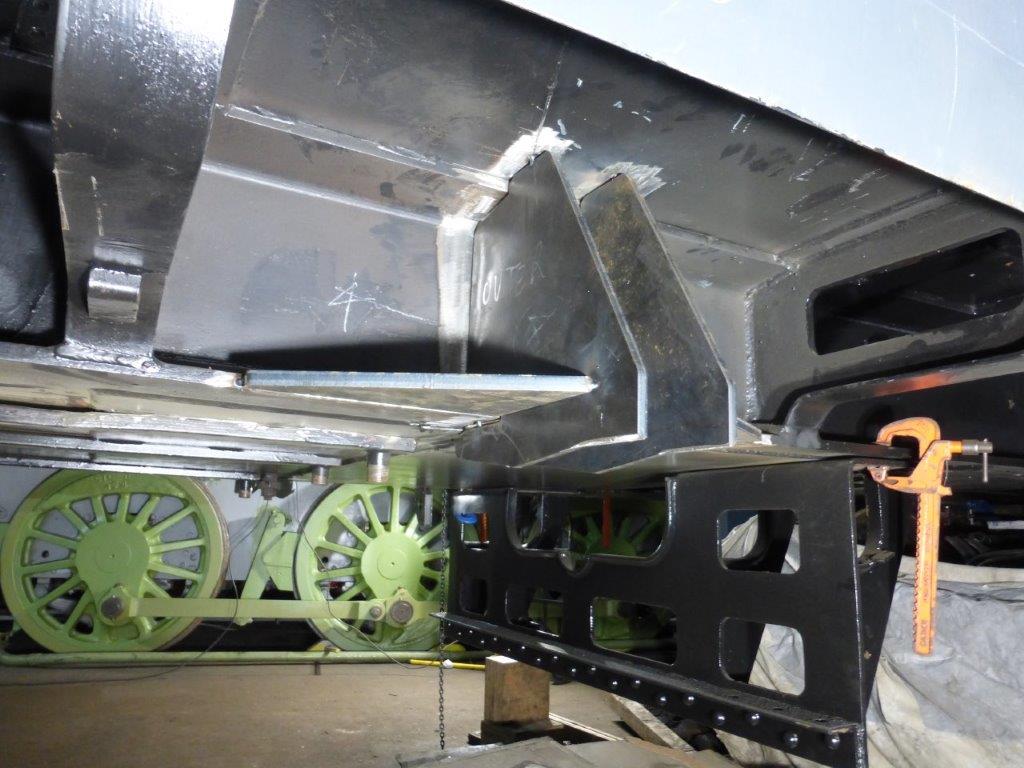
This (below) is the other side of the loco to the other photos but the arrangement is the same - here the spreader plate is held in position to allow it to be tacked / welded in. This spreader is designed to keep the cheek plates apart in the event of serious deceleration, it also shares the load of each cheek plate.
The load path of the shear plates between the cheek plates is completed by a yet-to-be added second spreader coincident with the bottom web of the longitudes. It is omitted at present to allow the bolting plate to be added without the spreader getting in the way.
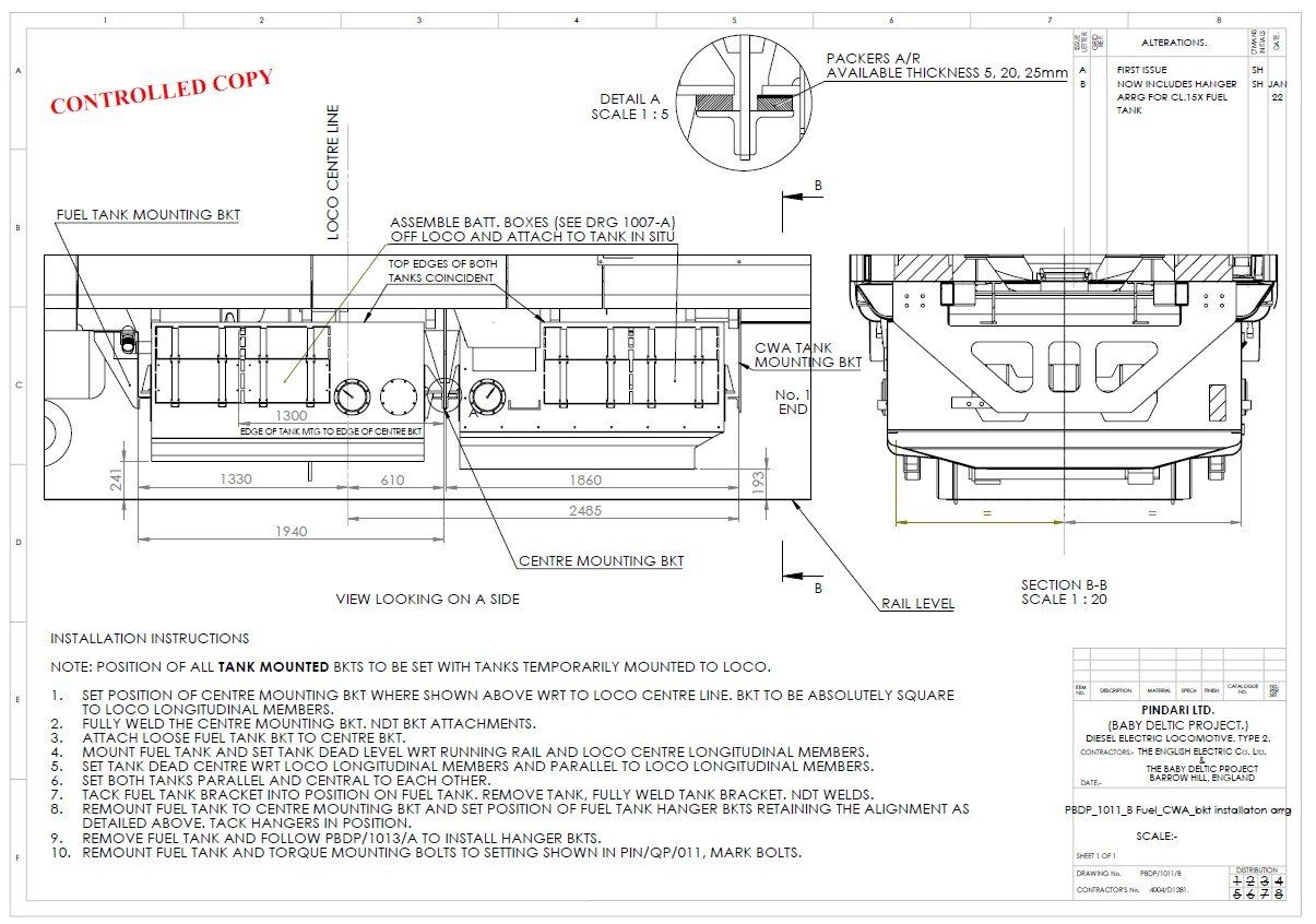
A manufacturing drawing of the fuel tank (to the left of the drawing on this arrangement).