News, 18 February 2023
News, 18 February 2023
Over the last couple of weeks all of the buffer valances have been rolled ready for fitting. The driver's side of no. 2 end has now been fitted and the three photos below show the progress.
The laser line is to mark the bottom edge of the panel beneath the nose end door and was previously used to set the reference to the buffer centre line in both horizontal and vertical planes - the lines can be seen extended onto the loco body.
The hydraulic jacks are there to correct for an uneven rail level by lifting under the bufferbeam and dragbox, there no point using a laser level if the loco itself isn't level.
This photo was taken before the panel was rolled, when the panel was offered up to set the start and end points of the roll - seen marked in chalk to the right of the ovoid cut-out.
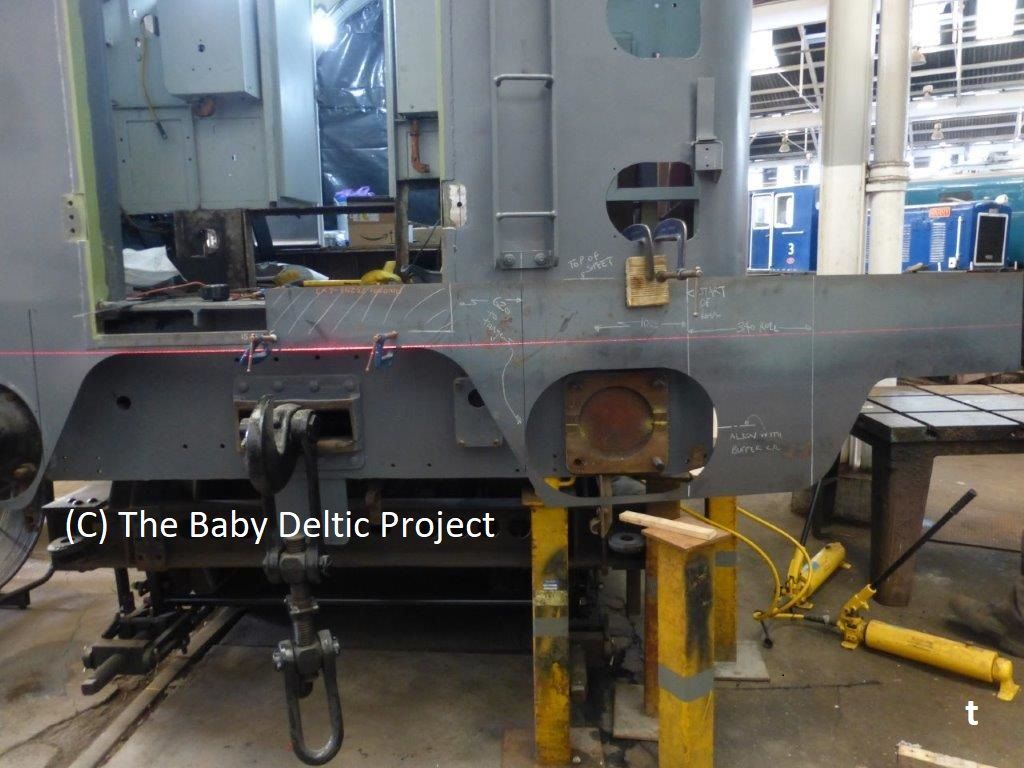
Once rolled, the panel is tacked in place at the loco centre line (left-hand end in this photo), supplemented by clamps to stop it levering down as it is fitted. The panel is pushed into place and at each point tacked and the re-checked for level and what is now becoming a compound bend.
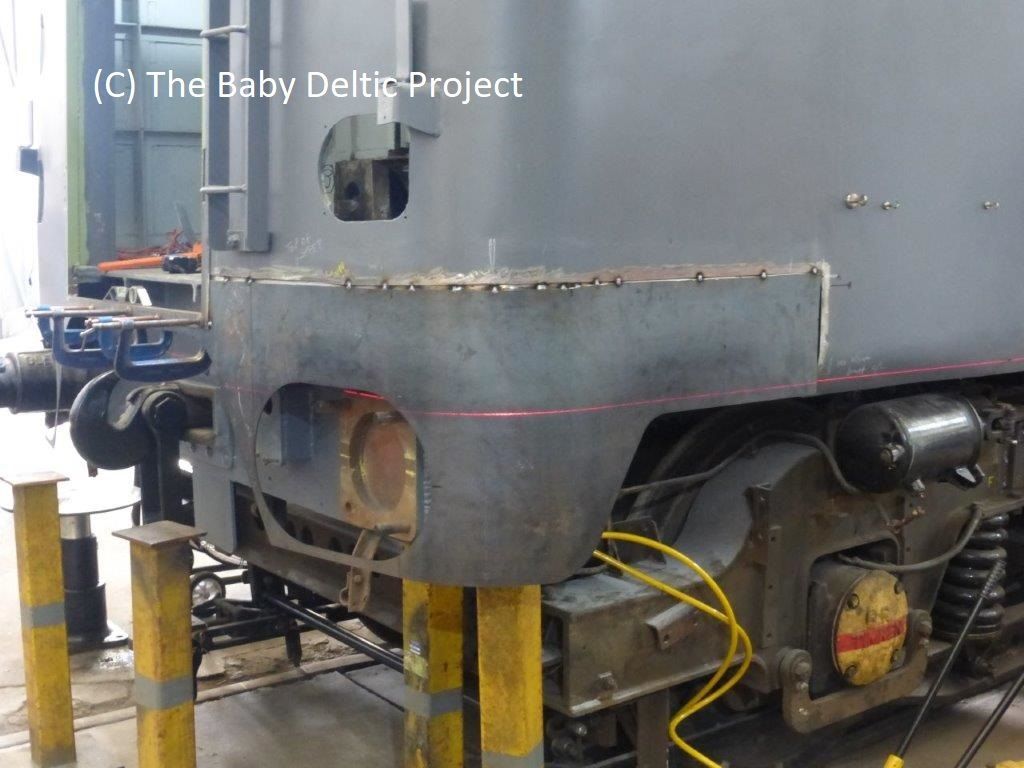
After fitting the loco was turned to allow the other end valances to be fitted. This photo is the same end (no. 2 end) as the previous two photos but it now faces the turntable. Seen here after the tumblehome has been added and the first coat of paint has gone on.