News, 25 August 2023
News, 25 August 2023
Last week one or two people expressed their delight at our bravery in cutting new metal out to fit grilles. Encouraged by our success we have done some more this week.
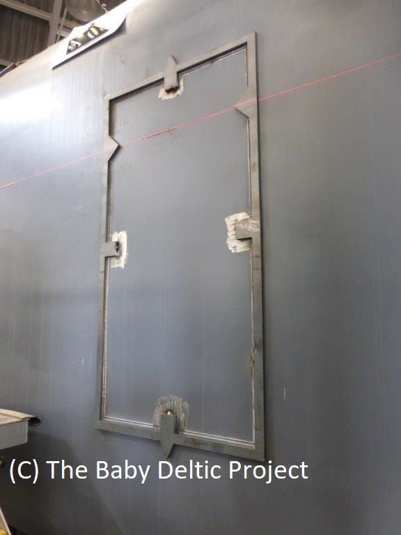
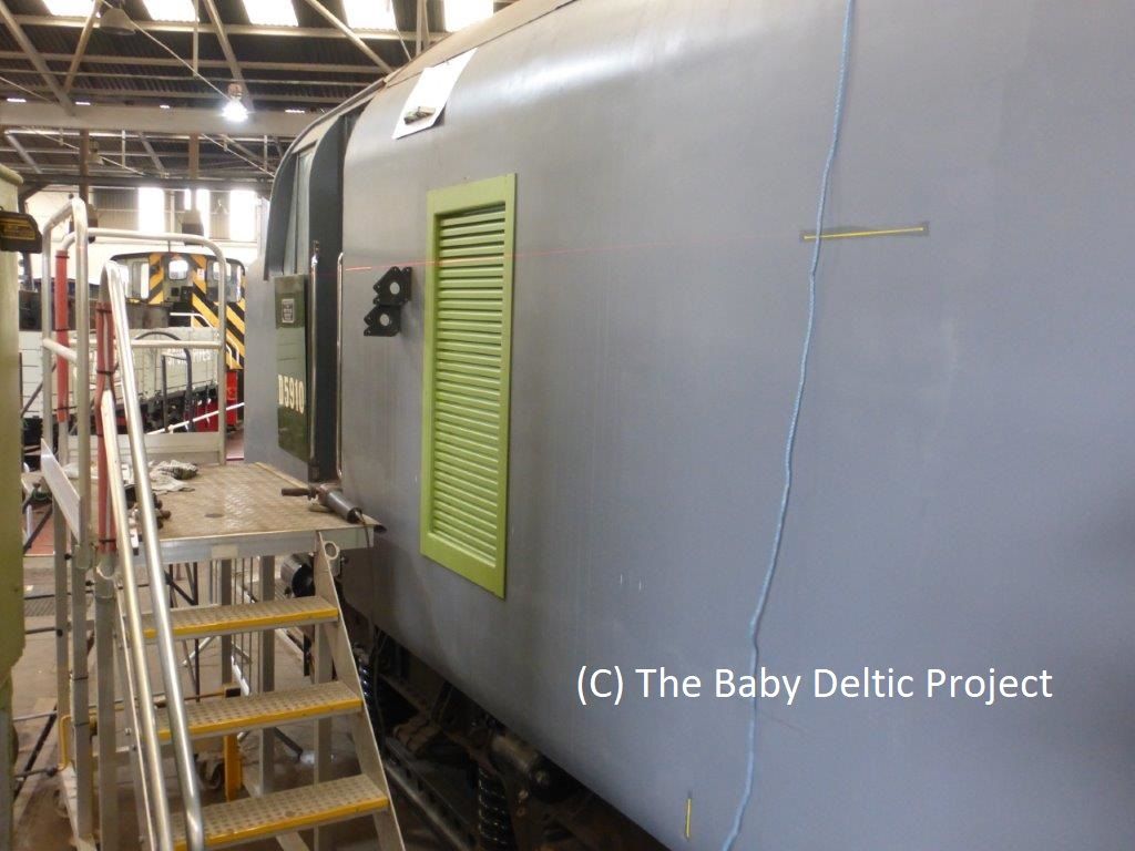
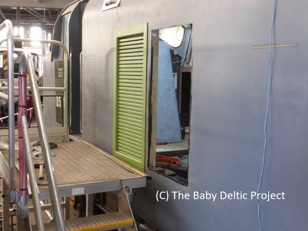
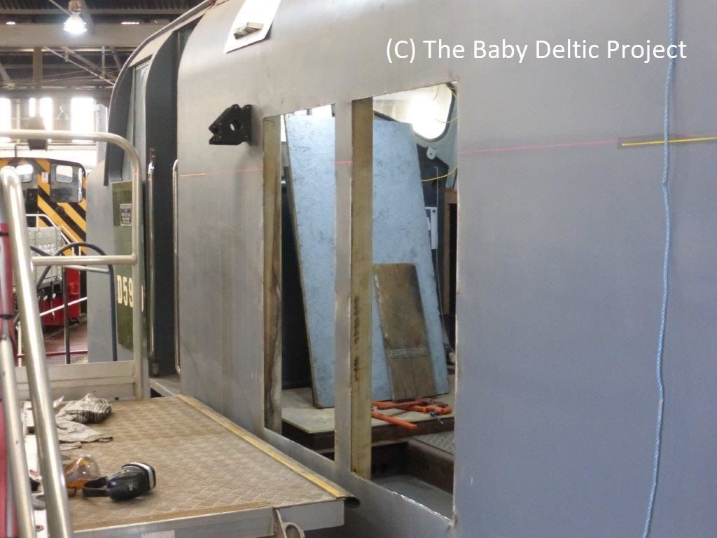
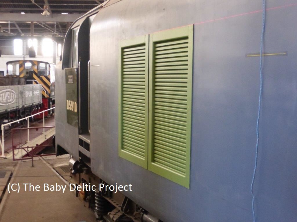
The three sequences of photos in this week's update detail the work to install two of the five bodyside grilles which provide air to the engine room.
The first set show the template for cutting out the body. The tabs on the inside are used to weld the template to the body so that it doesn't move during cutting, the arrow heads on the horizontal rails mark the centre of the cut out and the arrow heads on the verticals mark the datum. The datum used for the vertical positioning is an imaginary line drawn between the sill of the cab droplights. This has been compared to numerous photos to get the position right. No drawings of the cut-outs exist in the EECo / RDDS collection......
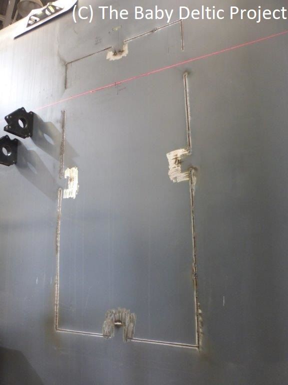
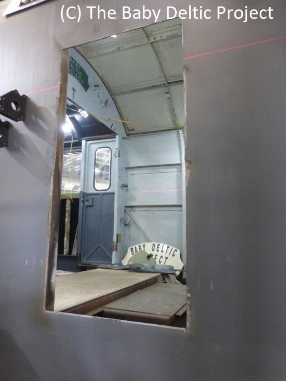
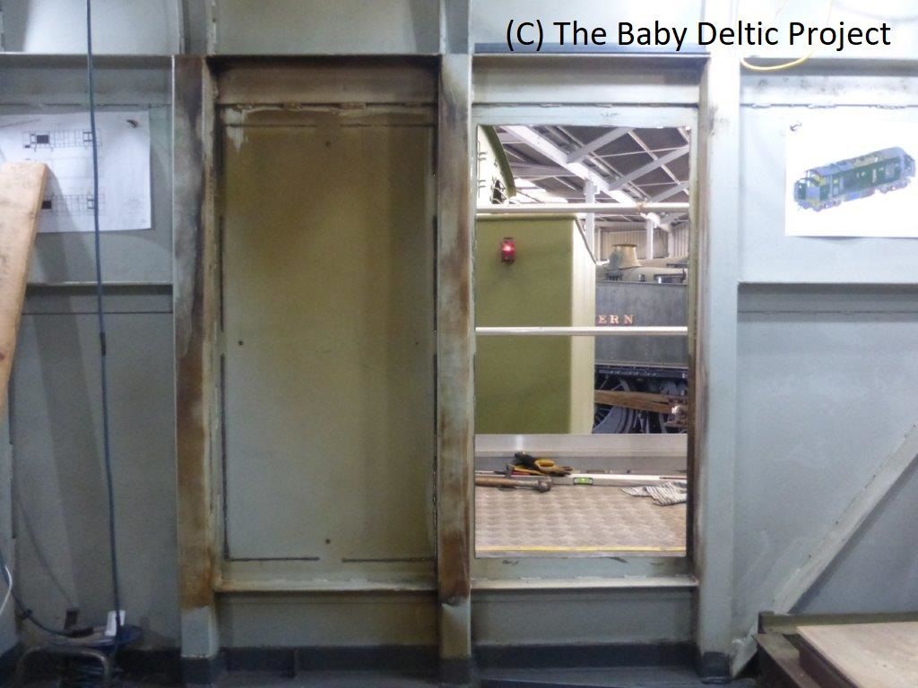
The major cuts were made with a plasma cutter leaving the template attached to the body, the template is then removed and the final cuts made with a slitting disc in a grinder. This leaves a hole in the body.
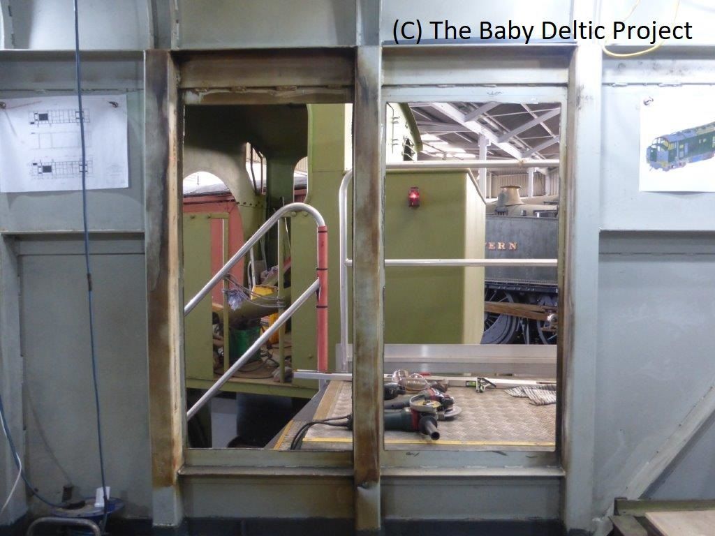
The photos below show the (trial) fit of the first grille, the second cut out and both grilles being trial fitted.
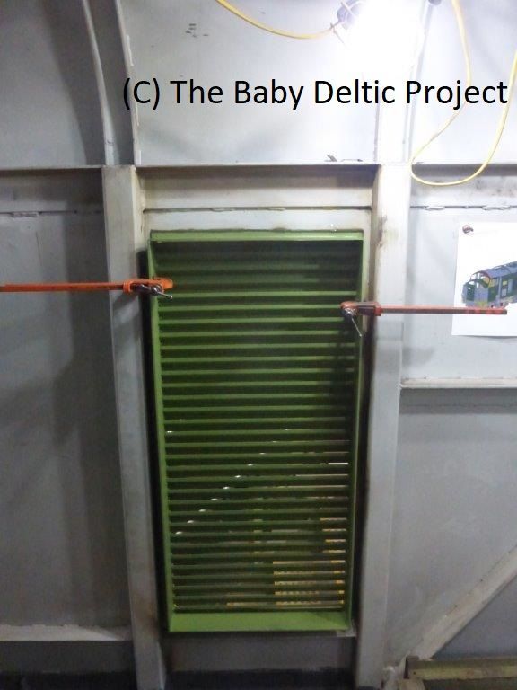
The final selection are taken from inside the loco and show one hole, two holes and then the first grille trial fit. The orange Carver clamps are stopping the grille falling out whilst its alignment is confirmed.
To put all of this into some kind of design perspective, the uprights either side of the grilles form part of the loco superstructure and their position was fixed before we even started to remove the body from the donor loco.
Did they fit / are they in the right place? Yes.
