News, 26 June 2023
News, 26 June 2023
The electrical control cubicle is nearing the point at which we can start to refit the control gear. The one fundamental alteration to the internal layout has been the need to incorporate the (new, electronic) load regulator. This will go on the centre 'row' at the extreme left in the photo below.
The whole cubicle has had several stages of cleaning, being stripped back to bare metal in places, before coats of primer and undercoat are applied as seen below.
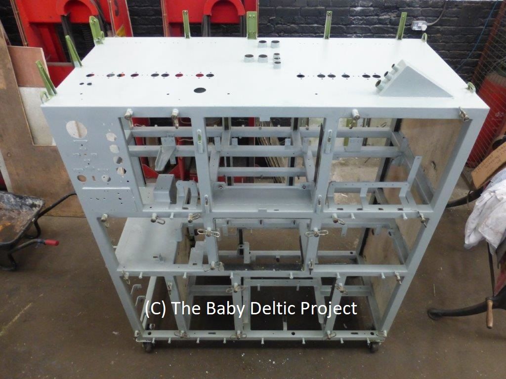
The only other noticeable change from the OE arrangement is that one of the relay mountings has been relocated. The upper rail in the photo below used to be where the load regulator will now go so it's been moved and inverted. It will carry five NR28 relays as it did before, as a fringe benefit it's now closer to the other NR28 relays so they can chat to each other.
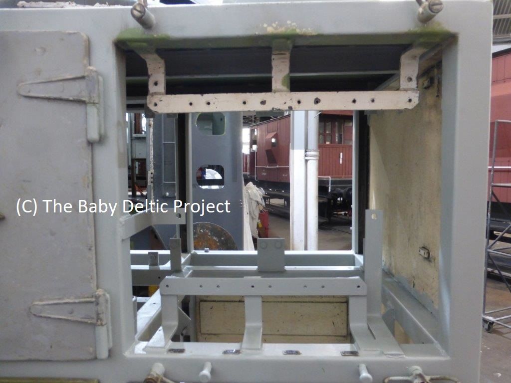
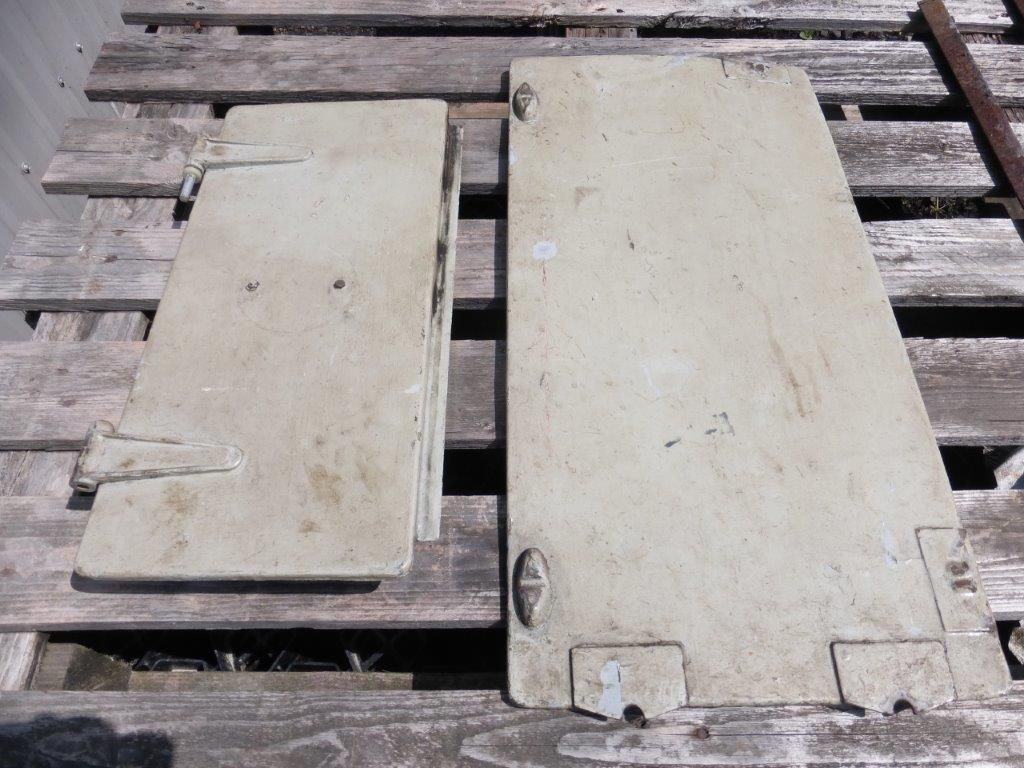
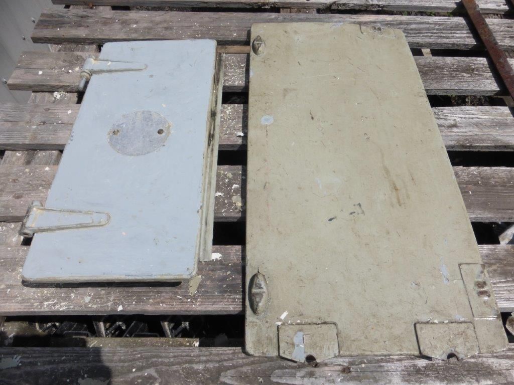
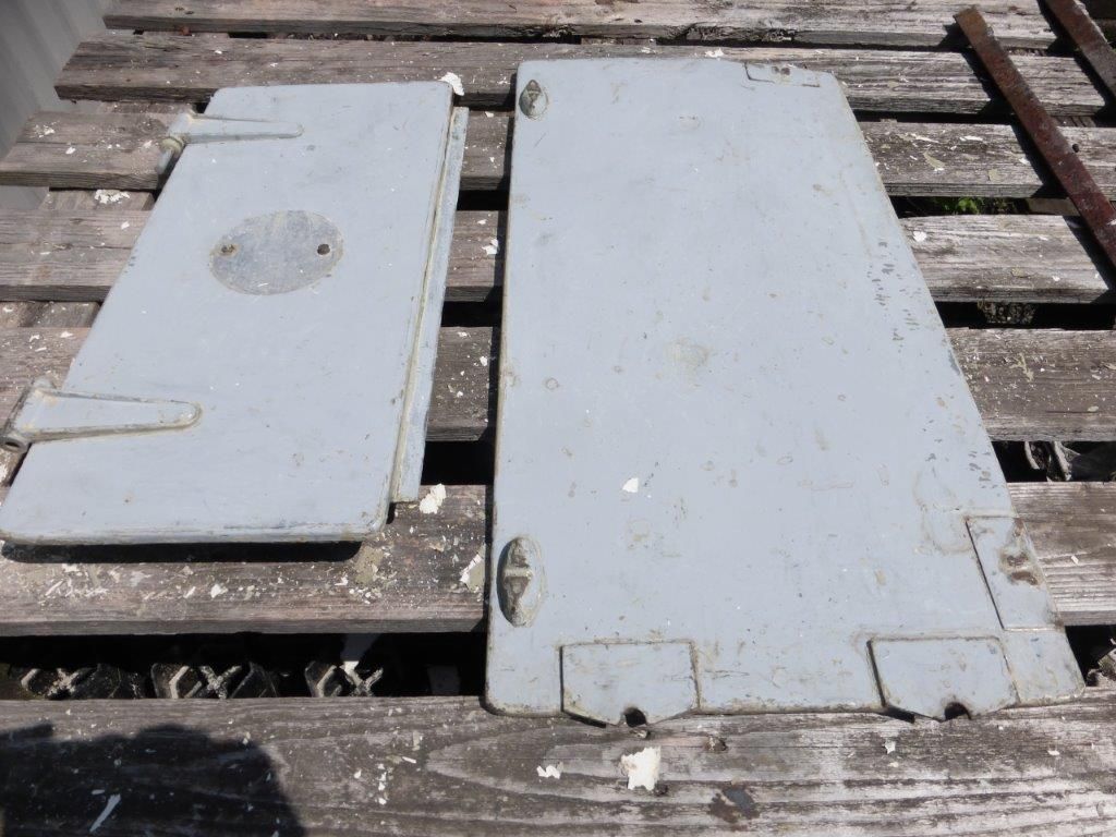
The sequence below shows two of the many control cubicle doors in a before and after state to show the effects of a decent clean and scrape.
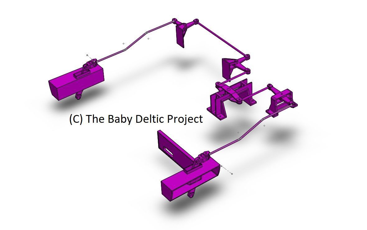
The parking brake arrangement on the recreated loco has been a headache. A wheel in the cab turns a lead screw to move a trunnion and pull four brake blocks (two per side) onto the wheels. It's a standard thing except that everything is reversed on our loco. This is because there wasn't enough room under the cab floor to get the linkage in. To beat this into submission we've had to put some of the linkage in the nose end.
Seen in the screenshot below are the parking brake lead screw mounting the reversing lever and pull-rods for the secondman's side and the two bell-cranks and pull-rods for the driver's side. All of the levers can move freely to take account of the potential for the loco to be on a curve when the parking brake is applied. Both the reversing lever and the first bell-crank have a longer input than output lever - this increases the leverage ratio and ups the force applied to the wheel tread a little.
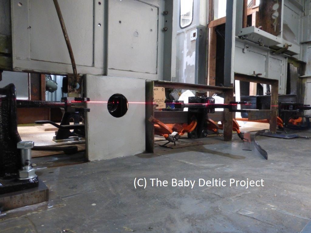
The photo below is taken from the nose looking towards the cab, the laser line is to confirm the alignment and set the position of the yokes which hold the pull-rods. Missing from the photo is the chain and sprocket which rotate the lead screw - they sit on the end of the lead screw just on the nose side of the black hole.
